
Cosmic Ray Propagation
This example shows how to trace cosmic rays in a turbulent magnetic field. Everything is dimensionless and normalized following Cosmic ray propagation in sub-Alfvénic magnetohydrodynamic turbulence. The general dimensionless-unit and SI↔dimensionless normalization (including relativistic tracing and periodic boundaries) is covered in the Dimensionless Units and Normalization example; here we use the cosmic-ray-specific form of that normalization.
With
so one unit of distance equals one gyroradius. We trace with two solvers that share the same underlying physics: the classic
using TestParticle, StaticArrays, LinearAlgebra, Random, Statistics
import TestParticle as TP
using OrdinaryDiffEq
using CairoMakie
1. Cosmic-ray normalization
Each particle of charge
where
After normalization, with the velocity normalized by
where
The factor
The ratio
2. Magnetic fields
We use a uniform field for the single-particle sanity check, and a synthetic guide field plus transverse Fourier modes for the ensemble. The synthetic field mirrors a production run, where TP.build_interpolator(F, gridx, gridy, gridz, 1, TP.WrapExtrap()) and normalized by
B0 = 1.0
B_uniform(x) = SA[0.0, 0.0, B0]
E_zero(x) = SA[0.0, 0.0, 0.0]

param_uniform = prepare(E_zero, B_uniform; q = 1.0, m = 1.0)

function generate_turbulent_field(
        gridx, gridy, gridz; B0 = 1.0, amp = 0.3, n_modes = 6, kmax = 3, seed = 42
    )
    nx, ny, nz = length(gridx), length(gridy), length(gridz)
    F = zeros(3, nx, ny, nz)
    F[3, :, :, :] .= B0
    rng = MersenneTwister(seed)
    for _ in 1:n_modes
        k = rand(rng, -kmax:kmax, 3)
        while all(k .== 0)
            k = rand(rng, -kmax:kmax, 3)
        end
        phase = 2π * rand(rng)
        a = amp * randn(rng)
        for i in 1:nx, j in 1:ny, kk in 1:nz
            s = k[1] * gridx[i] + k[2] * gridy[j] + k[3] * gridz[kk] + phase
            F[1, i, j, kk] += a * cos(s)
            F[2, i, j, kk] += a * sin(s)
        end
    end
    return F
end

nx = ny = nz = 24
dx = 0.5
L = nx * dx
gridx = range(dx / 2, L - dx / 2; length = nx)
gridy = range(dx / 2, L - dx / 2; length = ny)
gridz = range(dx / 2, L - dx / 2; length = nz)

F = generate_turbulent_field(gridx, gridy, gridz; B0)
itp = TP.build_interpolator(F, gridx, gridy, gridz, 1, TP.WrapExtrap())
Bfunc(x) = itp(x) ./ B0 # normalize: background guide field -> 1

param = prepare(E_zero, Bfunc; q = 1.0, m = 1.0);
3. Solver consistency: trace_normalized! vs Boris
Both solvers advance the same normalized equations param (and therefore the same field evaluation). We check that they agree.
3.1 Uniform field: both give a circle of radius 1
A particle launched with
stateinit = [0.0, 0.0, 0.0, 1.0, 0.0, 0.0] # v = 1 -> r_L = 1
tspan0 = (0.0, 2π)

prob_rk = ODEProblem(trace_normalized!, stateinit, tspan0, param_uniform)
sol_rk = solve(prob_rk, Vern9(); reltol = 1.0e-9, abstol = 1.0e-11)

prob_b = TraceProblem(stateinit, tspan0, param_uniform)
sol_b = solve(
    prob_b, TP.MultistepBoris4(n = 4);
    dt = 2π / 40
);
The initial gyroradius from each solver (computed at the final state) should be ~1.
function rL_of(sol, Bfunc)
    xv = sol isa AbstractVector ? sol : sol.u[end]
    x = xv[SA[1, 2, 3]]; v = xv[SA[4, 5, 6]]
    B = Bfunc(x); Bmag = norm(B); b̂ = B ./ Bmag
    vpar = b̂ ⋅ v; vperp = v - vpar * b̂
    return norm(vperp) / Bmag
end
println("r_L (RK)  = ", round(rL_of(sol_rk, B_uniform); digits = 4))
println("r_L (Boris) = ", round(rL_of(sol_b, B_uniform); digits = 4))

f = Figure(fontsize = 18)
ax = Axis(
    f[1, 1], title = "Perpendicular orbit (r_L = 1): both solvers",
    xlabel = "X", ylabel = "Y", aspect = DataAspect()
)
lines!(ax, sol_rk, idxs = (1, 2); color = :steelblue, linewidth = 2, label = "RK (trace_normalized!)")
lines!(ax, sol_b[1, :], sol_b[2, :]; color = :tomato, linestyle = :dash, linewidth = 2, label = "Boris")
axislegend(ax)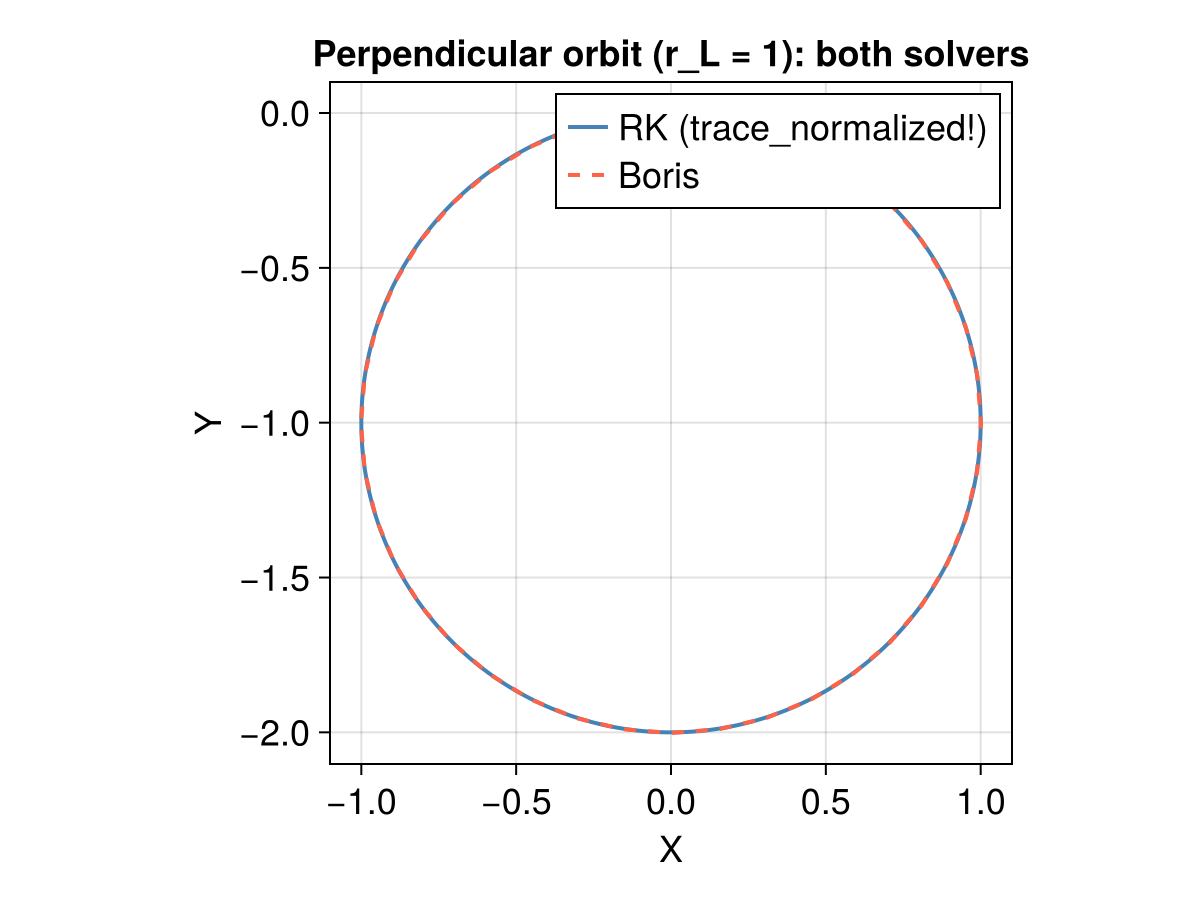
3.2 Turbulent field: single particle, both solvers
We now inject one particle into the synthetic turbulent field and integrate a few gyroperiods with both solvers, using the identical initial state and param. We overlay the X–Y projections and report the maximum separation relative to the gyroradius — it is tiny, confirming the solvers agree.
x0 = SA[0.5L, 0.5L, 0.5L]
Bv = Bfunc(x0); b0 = normalize(Bv)
e1 = SA[0.0, -b0[3], b0[2]]
e1 = norm(e1) > 1.0e-8 ? normalize(e1) : SA[0.0, 1.0, 0.0]
v0 = e1 + 0.3 * b0                 # |v| ≈ 1, mostly perpendicular
stateinit_t = collect(vcat(x0, v0))
tspan_t = (0.0, 2π * 3)

prob_rk_t = ODEProblem(trace_normalized!, stateinit_t, tspan_t, param)
sol_rk_t = solve(prob_rk_t, Vern9(); reltol = 1.0e-9, abstol = 1.0e-11)

prob_b_t = TraceProblem(stateinit_t, tspan_t, param)
sol_b_t = solve(
    prob_b_t, TP.MultistepBoris4(n = 4);
    dt = 2π / 80, trajectories = 1
)

trange = range(tspan_t..., length = 201)
rk_xy = [sol_rk_t(t)[SA[1, 2]] for t in trange]
bc_xy = [sol_b_t(t)[SA[1, 2]] for t in trange]
sep = maximum(norm(sol_rk_t(t)[SA[1, 2, 3]] - sol_b_t(t)[SA[1, 2, 3]]) for t in trange)
println("Max position separation / r_L0 (turbulent, 3 gyroperiods) = ", round(sep; digits = 4))
@assert sep < 0.2 "RK and Boris solvers disagree unexpectedly (sep = $sep)"

f = Figure(fontsize = 18)
ax = Axis(
    f[1, 1], title = "Turbulent-field trajectory: both solvers",
    xlabel = "X", ylabel = "Y", aspect = DataAspect()
)
lines!(ax, first.(rk_xy), last.(rk_xy); color = :steelblue, linewidth = 2, label = "RK (trace_normalized!)")
lines!(ax, first.(bc_xy), last.(bc_xy); color = :tomato, linestyle = :dash, linewidth = 2, label = "Boris")
axislegend(ax)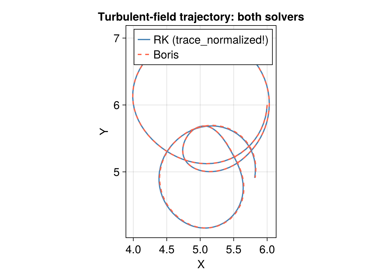
4. Constant-initial-gyroradius injection
The key physics choice for an energy scan: we fix the initial gyroradius
where
prob_func receives (prob, ctx) where ctx.rng is a per-trajectory RNG, and returns a remaked problem with the new initial state.
function make_injection(Lx, Ly, Lz; rL = 1.0)
    function prob_func(prob, ctx)
        r = rand(ctx.rng, 5)
        x = Lx * (0.1 + 0.8 * r[1])
        y = Ly * (0.1 + 0.8 * r[2])
        z = Lz * (0.1 + 0.8 * r[3])
        loc = SA[x, y, z]

        Bvec = prob.p[4](loc)
        Bmag = norm(Bvec)
        b0 = Bvec ./ Bmag

        bperp1 = SA[0.0, -b0[3], b0[2]]
        n1 = norm(bperp1)
        bperp1 = n1 > 1.0e-8 ? bperp1 ./ n1 : SA[0.0, 1.0, 0.0]
        bperp2 = b0 × bperp1 |> normalize
        bperp1 = bperp2 × b0

        ϕ = 2π * r[4]
        μ0 = 0.999 * r[5]          # pitch-angle cosine in [0, 1)
        sinα = √(1 - μ0^2)
        sinϕ, cosϕ = sincos(ϕ)

        vperp_mag = rL * Bmag
        vperp = (bperp1 .* cosϕ .+ bperp2 .* sinϕ) .* vperp_mag
        vpar_mag = vperp_mag * μ0 / sinα
        v0 = vpar_mag .* b0 .+ vperp

        return remake(prob; u0 = [x, y, z, v0...])
    end
    return prob_func
end
make_injection (generic function with 1 method)5. Ensemble tracing (Boris)
We trace a small ensemble with MultistepBoris4 (4th-order gyrophase correction, 4 subcycles). In production this is where you would loop over the energy (rL) and pitch-angle (μ0) bins and the guide-field snapshots, writing each trajectory to a JLD2 file via save_output.
rL0 = 1.0
tspan = (0.0, 2π * 150)
prob_func = make_injection(L, L, L; rL = rL0)
prob = TraceProblem(stateinit, tspan, param; prob_func)

alg = TP.MultistepBoris4(n = 4)
dt = 2π / 40
sols = solve(
    prob, alg, EnsembleThreads();
    dt, saveat = 15 * dt, trajectories = 32, seed = 1234
);
6. Analysis
6.1 Trajectories, guiding center, and phase-space evolution
We plot a few trajectories together with their guiding centers (computed with get_gc_func), and for one trajectory show how the gyroradius and pitch-angle cosine evolve. The gyroradius starts at
gc = param |> get_gc_func

f = Figure(fontsize = 16, size = (700, 500))
ax = Axis3(f[1, 1], title = "Sample trajectories and guiding centers", aspect = :data)

for (i, sol) in enumerate(sols.u[1:4])
    x = sol[1, :]; y = sol[2, :]; z = sol[3, :]
    lines!(ax, x, y, z; color = Makie.wong_colors()[i], linewidth = 1.5)
    gcx = [gc(sol.u[k])[1] for k in eachindex(sol.u)]
    gcy = [gc(sol.u[k])[2] for k in eachindex(sol.u)]
    gcz = [gc(sol.u[k])[3] for k in eachindex(sol.u)]
    lines!(ax, gcx, gcy, gcz; color = Makie.wong_colors()[i], linestyle = :dash)
end

function phase_evolution(sol, Bfunc)
    n = length(sol.u)
    t = sol.t
    ρ = zeros(n)
    μ = zeros(n)
    for k in 1:n
        x = sol.u[k][SA[1, 2, 3]]
        v = sol.u[k][SA[4, 5, 6]]
        B = Bfunc(x)
        Bmag = norm(B)
        b̂ = B ./ Bmag
        vpar = b̂ ⋅ v
        vperp = v - vpar * b̂
        ρ[k] = norm(vperp) / Bmag
        μ[k] = vpar / norm(v)
    end
    return t, ρ, μ
end

t1, ρ1, μ1 = phase_evolution(sols.u[1], Bfunc)

f = Figure(fontsize = 16, size = (1000, 600))
axρ = Axis(f[1, 1], xlabel = "t / 2π", ylabel = L"r_L")
axμ = Axis(f[2, 1], xlabel = "t / 2π", ylabel = "μ")
lines!(axρ, t1 ./ (2π), ρ1; color = :steelblue, label = L"r_L")
hlines!(axρ, [rL0]; color = :tomato, linestyle = :dash)
lines!(axμ, t1 ./ (2π), μ1; color = :seagreen, label = "μ")
axislegend(axρ); axislegend(axμ)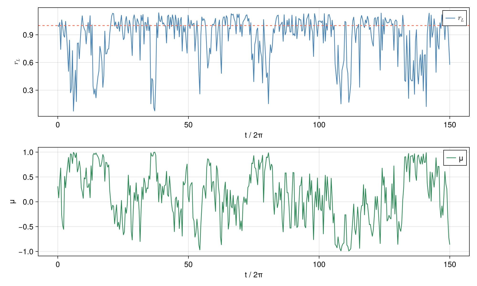
6.2 Energy scan: diffusion grows with gyroradius
Sweep over the initial gyroradius
rL_list = [0.5, 1.0, 2.0]
colors = Makie.wong_colors()

f = Figure(fontsize = 18, size = (1000, 600))
ax = Axis(
    f[1, 1], xlabel = "t / 2π", ylabel = "⟨|Δx|²⟩",
    title = "Mean squared displacement vs initial gyroradius"
)

for (j, rL) in enumerate(rL_list)
    pfunc = make_injection(L, L, L; rL)
    pscan = TraceProblem(stateinit, (0.0, 2π * 100), param; prob_func = pfunc)
    dt = 2π / 40
    ssols = solve(
        pscan, alg, EnsembleThreads();
        dt, saveat = 10 * dt, trajectories = 16, seed = 1234
    )
    nt = length(ssols.u[1].u)
    msr = zeros(nt)
    for sol in ssols.u
        r0 = sol.u[1][SA[1, 2, 3]]
        for k in 1:nt
            Δ = sol.u[k][SA[1, 2, 3]] - r0
            msr[k] += Δ ⋅ Δ
        end
    end
    msr ./= length(ssols.u)
    lines!(ax, ssols.u[1].t ./ (2π), msr; label = "r_L0 = $rL", color = colors[j])
end
axislegend(ax; position = :lt)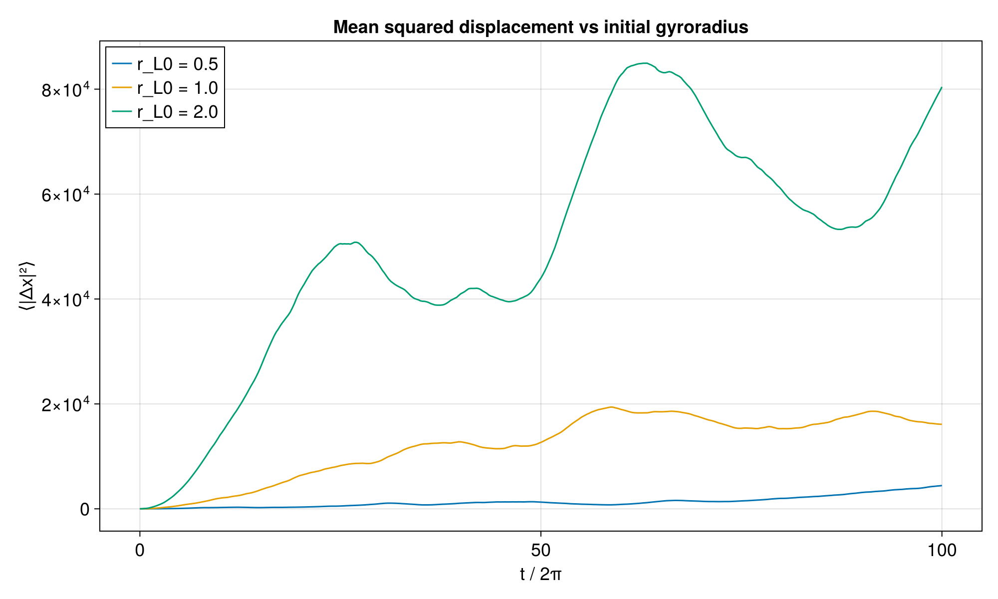
7. Production notes
For a real run you would replace the synthetic field with a snapshot loaded from disk and write the output to disk. The workflow maps as follows:
load_B(filedir, idx)/load_J(...)→ anFarray (3×nx×ny×nz).TP.build_interpolator(F, gridx, gridy, gridz, 1, TP.WrapExtrap()) ./ B0builds the periodic, normalized field.The
prob_funcabove is unchanged — it already scalesby the local so the injected is identical across snapshots and energies. After tracing, save per-trajectory diagnostics (guiding center,
, current density , curvature via TP.get_magnetic_properties) to JLD2, mirroring the productionsave_output.