19 Geometry
This chapter introduces the topology-related concepts in plasma physics, including ropes, knots, boundaries, and null points. Usually, observers and modelers have different views of topology because of the tools at hand: observers have probes which give measurements as a function of both time and space, while modelers have full spatial-temporal information under the given resolution. It always amazes me how observers can deduce the general picture of plasma structures with such limited data. Incorporating observation experience into physics as well as diagnosing numerical simulations with physics are our main goals in studing geometry.
Generally speaking, there are two ways of tackling the geometry problems: physics-based methods and statistical methods (classical and machine learning). We may find harmony when combining these two families and reach optimal results.
19.1 Local Coordinate System
Define the Jacobian \(\overleftrightarrow{G} = \nabla\mathbf{B}\) of the magnetic field.
Minimum Directional Derivative (MDD) Method: In the MDD method, local orthogonal coordinate directions can be obtained from eigenvectors of \(\overleftrightarrow{G}^\intercal\overleftrightarrow{G}\).
Minimum Gradient Analysis (MGA): In MGA, local orthogonal coordinate directions can be obtained from eigenvectors of \(\overleftrightarrow{G}\overleftrightarrow{G}^\intercal\).
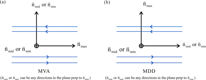
MGA produces a set of basis vectors that are analogous with the ones from Minimum Variance Analysis (MVA), with the eigenvector corresponding to the largest eigenvalue aligned with the vector that has maximal variation (which is denoted by \(\hat{L}_\mathrm{MGA}\)), the second one corresponding to the intermediate (\(\hat{M}_\mathrm{MGA}\)) and third the least variation (\(\hat{N}_\mathrm{MGA}\)). MDD produces a set of basis vectors where the eigenvector corresponding to the largest eigenvalue shows the direction of the displacement which produces the largest variation in \(\mathbf{B}\) (the cross-sheet direction in a Harris current sheet; \(\hat{L}_\mathrm{MDD}\)), idem with smaller eigenvalues (\(\hat{M}_\mathrm{MDD}\) and \(\hat{N}_\mathrm{MDD}\), respectively). Both of these eigensystems have the same eigenvalues, but the eigenvectors differ and are not necessarily aligned with each others. We note here that for a one-dimensional structure, both of these eigensystem have only one well-defined eigenvector, and that for a 1D current sheet structure, the well-defined eigenvectors of different bases are orthogonal to each others, as shown in Figure~\(\ref{fig:shirepro}\).
19.1.1 Dimensionality
MDD gives a way to define the local dimensionality of a structure from the eigenvalues of the matrix \(\overleftrightarrow{G}\overleftrightarrow{G}^\intercal\). The measures \(D_1\), \(D_2\), \(D_3\) describing the one-, two- or three-dimensionality of the magnetic field and are obtained from the ratios of square roots of the eigenvalues \(\lambda_i\) (\(i=1,2,3\), in descending order) of the MDD \(\overleftrightarrow{G}\overleftrightarrow{G}^\intercal\).
One kind of definitions for \(D_1\), \(D_2\), \(D_3\) are given below: \[ \begin{aligned} D_1 &= \frac{\sqrt{\lambda_1}-\sqrt{\lambda_2}}{\sqrt{\lambda_1}}\\ D_2 &= \frac{\sqrt{\lambda_2}-\sqrt{\lambda_3}}{\sqrt{\lambda_1}}\\ D_3 &= \frac{\sqrt{\lambda_3}}{\sqrt{\lambda_1}}. \end{aligned} \] These quantities are defined to lie in the range [0,1] and their sum is one. For \(D_1 \approx 1\), the magnetic field structure is primarily one-dimensional, such as a current sheet with \(\mathbf{B} \approx \mathbf{B}(z)\) for a direction \(z\) normal to the current sheet. Correspondingly, for \(D_2 \approx 1\), the structure is primarily a function of two coordinates, etc. These measures allow us to quantify whether or not the locally 2D treatment for neutral lines is well-founded.
If the eigenvalues are not well-separated, the directions obtained from MGA and MDD are ambiguous (Shi et al. 2019). For example, the current sheet with dimensionality 1, MGA obtains the field-aligned direction (above and below the current sheet), while MDD obtains the normal direction to the current sheet, with two other directions being ambiguous.1
Common representative structure:
- 1D: current sheet
- 2D: plasmoid, flux rope
- 3D: rare2
19.2 Reconnection Identification
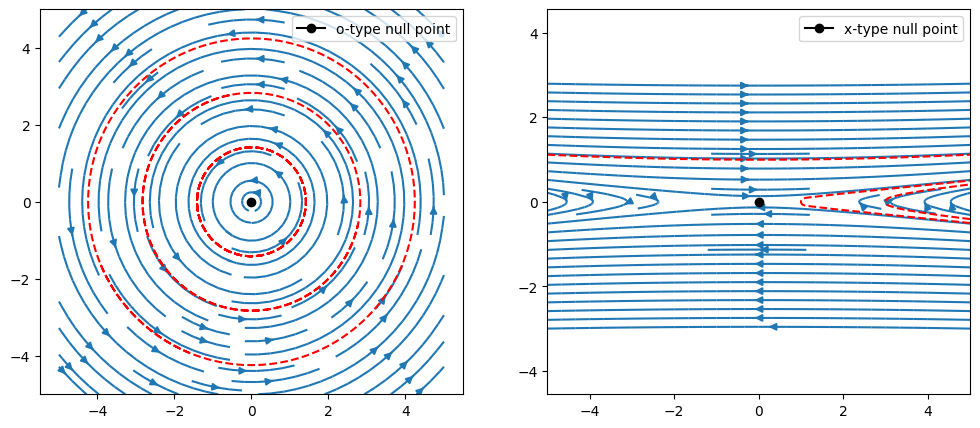
Here we present analytical fields for an X-point configuration and an O-point configuration, respectively.
19.2.1 2D
Identification of 2D reconnection sites is easy. Assume the out-of-plane direction being y, with \(B_y = \mathrm{const}\). The divergence-free condition gives \[ \frac{\partial B_x}{\partial x} + \frac{\partial B_z}{\partial z} = 0 \]
In the X-Z plane, we can define a flux function \[ \psi = \int B_x dz = - \int B_z dx \] then \[ \mathbf{B} = B_x\hat{x} + B_z\hat{z} = \hat{y}\times\nabla\psi \]
The null points are simple saddle points and extremas of the flux function.

19.2.2 3D
Identification of 3D reconnection sites is not easy.
Implement Lapenta’s method.
The four-field junction (FFJ) method is proposed by Laitinen+ 2006. It works decently on steady reconnection cases, but not when things change drastically.
19.2.3 Critical Points
Let us discuss the problem with topological definitions (following Kenneth Rohde Christiansen and Aard Keimpema). Critical points are points where the vector vanishes (i.e. \(\mathbf{v}=0\)). More rigidly speaking, critical points are stationary points that have a non-singular (i.e. no zero eigenvalues) Jacobian or vector gradient \(\nabla\mathbf{v}\). There are 6 different types of critical points, characterized by the behavior of nearby tangent curves. The position of these critical points can be found by searching all cells in the flow field. Critical points only occur in cells whree all components of the vector pass through zero. In order to find the exact location of the critical point we will have to do interpolations.
We can then classify these by looking at the eigenvalues of the Jacobian matrix. The Jacobian matrix for a 2D vector \((u,v)\) is given by \[ \frac{\partial(u,v)}{\partial(x,y)}\Bigg\rvert_{x_0, y_0} = \begin{pmatrix} \partial_x u & \partial_y u \\ \partial_x v & \partial_y v \end{pmatrix}\Bigg\rvert_{x_0, y_0} \tag{19.1}\]
As seen in Figure 19.4 these 6 different types are classified by the sign of the real and imaginary part of the eigenvalues. The real part of the eigenvalue gives rise to an attraction (if \(RE < 0\)) or a repulsion (if \(RE > 0\)). The imaginary part of the eigenvalue give rise to a rotation of vector field around the critical point. When we have an imaginary eigenvalue we are left with an entirely rotational vector field around the critical point.
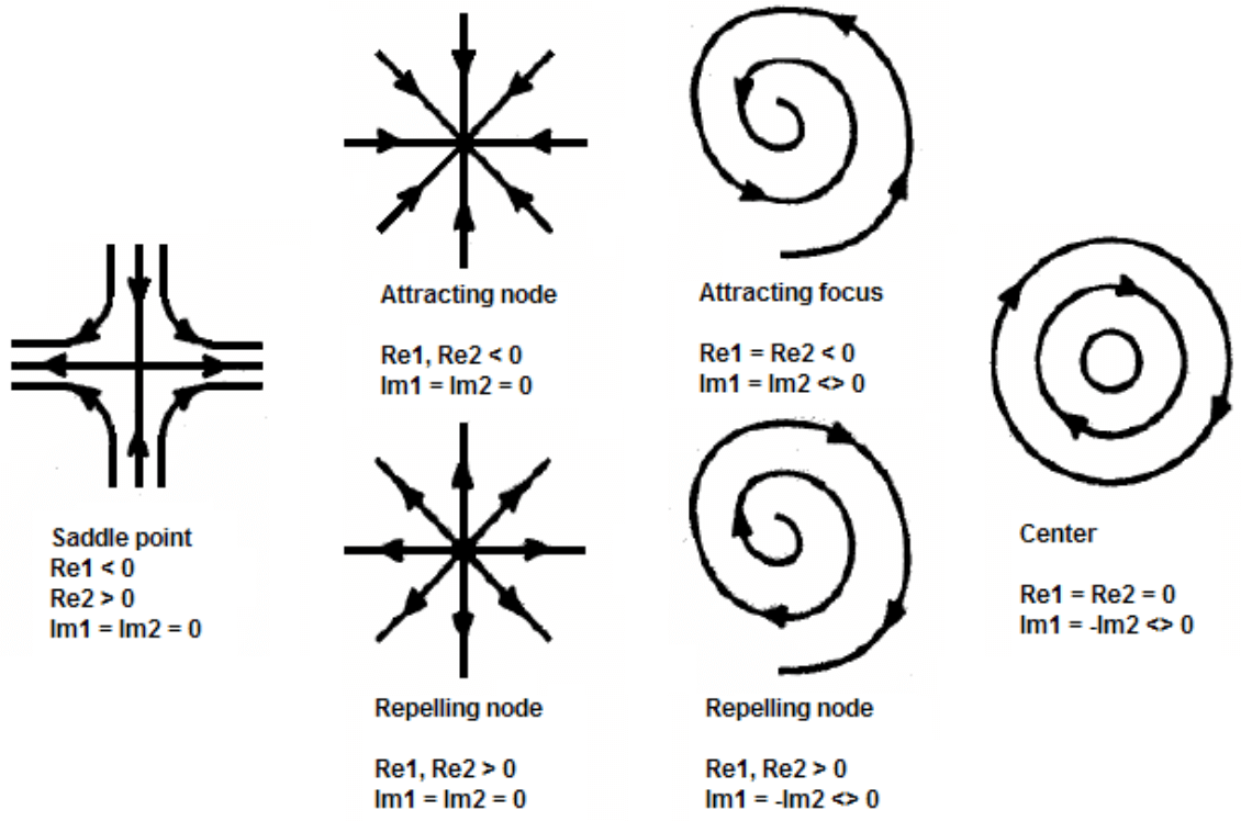
The most important critical point is the saddle point here we have a combination of attraction in one direction and repulsion in the other. The importance of saddle points as we shall see in the next section is that the tangent curves near a critical point determine the global structure of the flow.
A critical point is called hyperbolic if it does not have any eigenvalues with zero real part. Hyperbolic critical points are structurally stable, i.e., a small perturbation does not change their topology.
Besides critical points there are also so-called attachment/detachment nodes. These are points on the wall of an object where tangent curves terminate or begin.
In 3D, the most common (i.e., nondegenerate) types of critical points are sources, sinks, repelling saddles, and attracting saddles, visualized in Figure 19.5 ((Bujack et al. 2021)). Each of these types may imply a rotating pattern in a certain plane depending on the presence of eigenvalues with nonzero imaginary part. This gives rise to the eight cases shown in the figure. A 2D separatrix and two 1D separatrices originate or terminate at a saddle (if the 2D separatrix originates at the saddle, then the 1D separatrices terminate at the saddle, and vice-versa). The directions along which the separatrices approach the saddle are given by the eigenvectors of \(\nabla v\). The 1D separatrices are computed by placing two seeds at a small user-defined offset of the saddle in the direction of the eigenvectors of \(\nabla v\) corresponding to the eigenvalue whose sign appears only once. The trajectories from these seeds are integrated as explained above. The 2D separatrix is computed by placing eight seeds at a small user-defined offset of the saddle in the plane spanned by the eigenvectors of ∇v corresponding to the eigenvalues whose signs appear twice. These seeds are the base for integrating a surface — the separatrix.
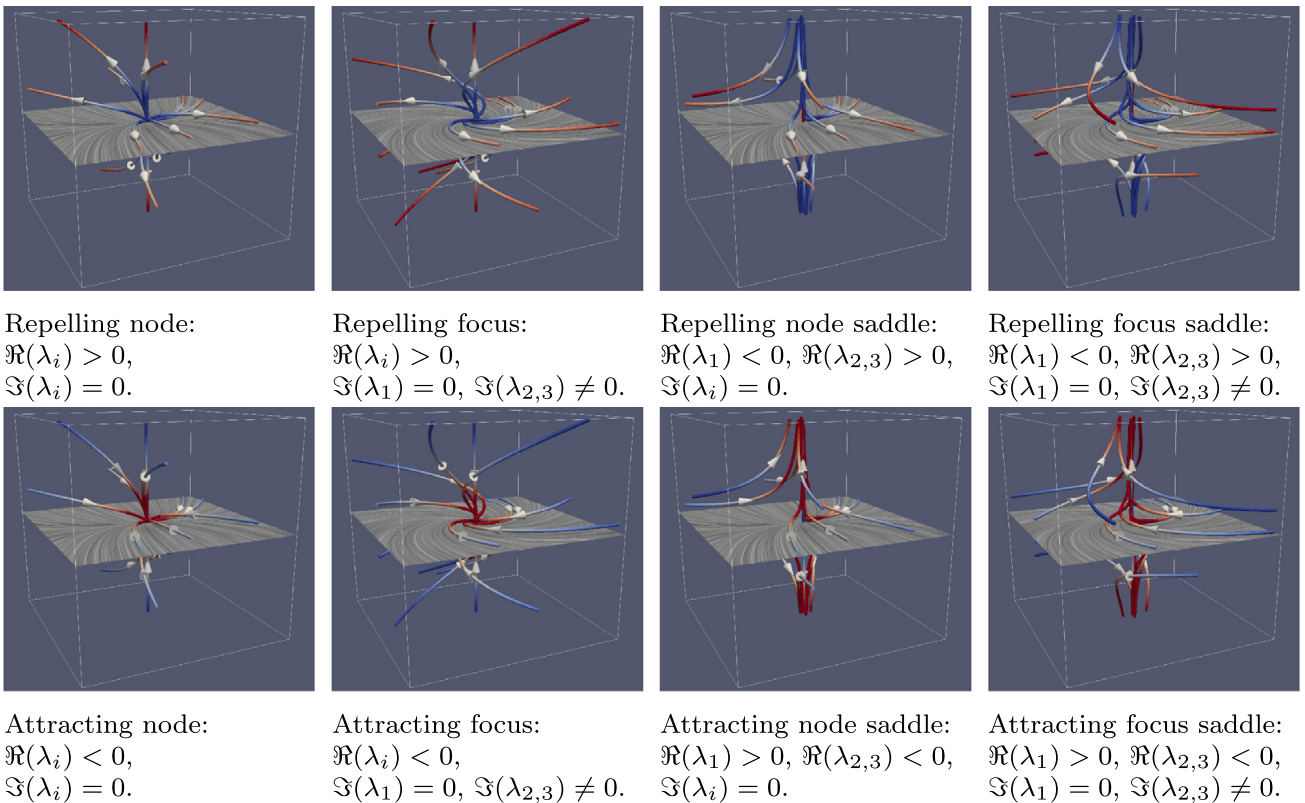
The most important input parameters are the distance in which the separatrices are seeded away from the saddles and the parameters that are handed off to the streamline and streamsurface integrators, like step sizes and maximum number of steps.
19.2.4 Separatrix
In scientific visualization, we treat vector fields defined on a discrete set of points in a grid and interpolate linearly or multilinearly within the cells. Since piecewise linear or multilinear functions are Lipschitz continuous, streamlines always exist uniquely.
A skeleton of a flow field is a figure containing the critical points of the flow field and the so-called integral curves connecting them. An integral curve can be thought of as the path a test particle takes when released infinitesimally close to a critical point. By adding e.g. an arrow the direction of the integral curves can be displayed; giving a global image of the flow. In the topology context, the skeleton is known as the separatrix. Separatrices are solutions which differ from their neighbors in their limit sets (?) or in their behavior in the large (?). Separatrices include critical points, periodic orbits, and invariant manifolds of saddles.
In practice, separatrices are constructed by
- Detecting critical points analytically in each cell
- Classifying them based on the eigenvalues of their Jacobian
- Seeding separatrices in a small offset of the saddles in the direction of their eigenvectors
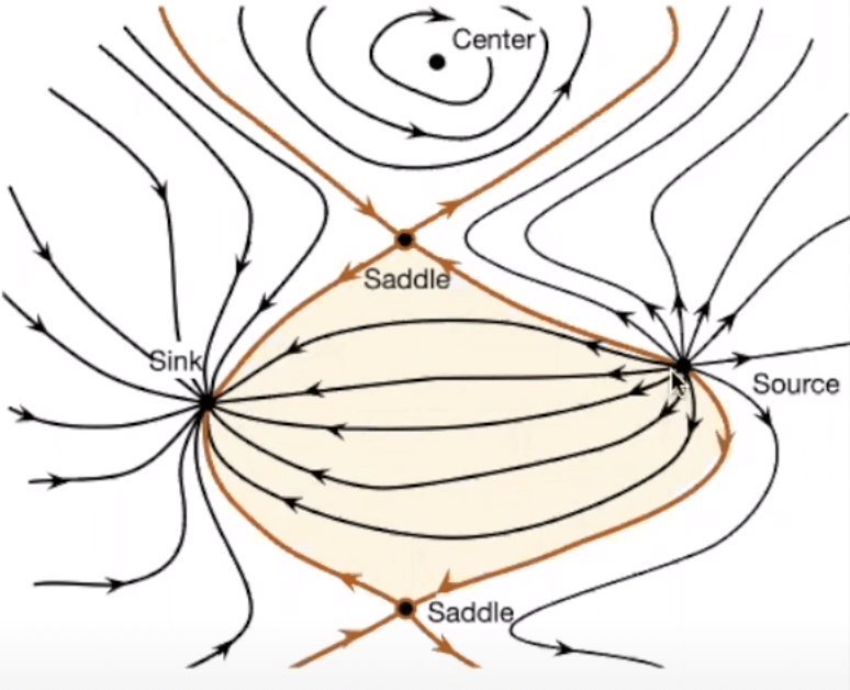
In 3D, instead of lines we may have separatrix surfaces.
19.3 Helicity
In fluid dynamics, helicity is, under appropriate conditions, an invariant of the Euler equations of fluid flow, having a topological interpretation as a measure of linkage and knottedness of vortex lines in the flow (Moffatt 1969).
Let \(\mathbf{u}(x,t)\) be the velocity field and \(\nabla\times\mathbf{u}\) the corresponding vorticity field. Under the following three conditions, the vortex lines are transported with (or “frozen in”) the flow:
- the fluid is inviscid;
- either the flow is incompressible (\(\nabla\cdot\mathbf{u}=0\)), or it is compressible with a barotropic relation \(p=p(\rho)\) between pressure \(p\) and density \(\rho\);
- any body forces acting on the fluid are conservative. Under these conditions, any closed surface \(S\) on which \(n\cdot(\nabla\times\mathbf{u})=0\) is, like vorticity, transported with the flow.
Let \(V\) be the volume inside such a surface. Then the helicity in \(V\) is defined by \[ H=\int_{{V}}{\mathbf{u}}\cdot\left(\nabla\times\mathbf{u}\right)\,dV \tag{19.2}\]
For a localised vorticity distribution in an unbounded fluid, \(V\) can be taken to be the whole space, and \(H\) is then the total helicity of the flow. \(H\) is invariant precisely because the vortex lines are frozen in the flow and their linkage and/or knottedness is therefore conserved, as recognized by Lord Kelvin (1868). Helicity is a pseudo-scalar quantity: it changes sign under change from a right-handed to a left-handed frame of reference; it can be considered as a measure of the handedness (or chirality) of the flow. Helicity is one of the four known integral invariants of the Euler equations; the other three are energy, momentum and angular momentum.
The invariance of helicity provides an essential cornerstone of the subject topological fluid dynamics and MHD, which is concerned with global properties of flows and their topological characteristics.
19.4 Magnetic Helicity
The helicity of a smooth vector field defined on a domain in 3D space is the standard measure of the extent to which the field lines wrap and coil around one another. As to magnetic helicity, this “vector field” is magnetic field. It is a generalization of the topological concept of linking number to the differential quantities required to describe the magnetic field. As with many quantities in electromagnetism, magnetic helicity for describing magnetic field lines is closely related to fluid mechanical helicity for describing fluid stream lines.
If magnetic field lines follow the strands of a twisted rope, this configuration would have nonzero magnetic helicity; left-handed ropes would have negative values and right-handed ropes would have positive values.
Formally, \[ H=\int\mathbf{A}\cdot\mathbf{B}\mathrm{d}\mathbf{r}^3 \tag{19.3}\] where
- \(H\) is the helicity of the entire magnetic field
- \(\mathbf{B}\) is the magnetic field strength
- \(\mathbf{A}\) is the vector potential of \(\mathbf{B}\) and \(\mathbf{B}=\nabla\times\mathbf{A}\)
Magnetic helicity has units of \(\text{Wb}^2\) in SI units and \(\text{Mx}^2\) in Gaussian Units. Note that \(\mathbf{A}\cdot\mathbf{B}\) should not be considered as “helicity density” because of gauge freedom.
It is a conserved quantity in electromagnetic fields, even when magnetic reconnection dissipates energy (Woltjer 1958). The concept is useful in solar dynamics and in dynamo theory. Helicity is approximately conserved during magnetic reconnection and topology changes. Helicity can be injected into a system such as the solar corona. When too much builds up, it ends up being expelled through coronal mass ejections. The simple proof in ideal MHD can be found on Wikipedia.
Magnetic helicity is a gauge-dependent quantity, because \(\mathbf{A}\) can be redefined by adding a gradient to it (gauge transformation): \[ \mathbf{A}^\prime = \mathbf{A} + \nabla\phi \]
However, for perfectly conducting boundaries or periodic systems without a net magnetic flux, the magnetic helicity is gauge invariant. A gauge-invariant relative helicity has been defined for volumes with non-zero magnetic flux on their boundary surfaces. If the magnetic field is turbulent and weakly inhomogeneous a magnetic helicity density and its associated flux can be defined in terms of the density of field line linkages.
The topological properties of a magnetic field are interpreted in terms of magnetic helicity. The total helicity of a collection of flux tubes arises from the linking of flux tubes with one another (mutual helicity) and the internal magnetic structure of each flux tube (self-helicity). Reconnection changes the topology and magnetic connectivity of flux tubes. This can also be viewed as a redistribution of self- and mutual helicities. If total magnetic helicity is approximately conserved, it is possible to put quantitative limits upon the changes in self- and mutual helicities. This can be interpreted as the change in magnetic flux tube linkage (due to reconnection) and amount of twist present in the reconnected flux tubes. [Wright & Berger, 1989]
Simple examples:
- A single untwisted closed flux loop has \(H=0\).
- A single flux rope with a magnetic flux of \(\phi\) that twists around itself \(T\) times has a helicity of \(H = T\phi^2\).
- Two interlinked untwisted flux loops with fluxes \(\phi_1\) and \(\phi_2\) have \(H=\pm2\phi_1\phi_2\) where the sign depends on the sense of the linkedness.
There are generalizations to allow for gauge-invariant definitions of helicity. [Berger & Field (1984)] defined the relative magnetic helicity to be \[ H = \int_V \mathbf{A}\cdot\mathbf{B} - \mathbf{A}_0\cdot\mathbf{B}_0 dV \tag{19.4}\] where \(\mathbf{B}_0=\nabla\times\mathbf{A}_0\) is the potential field inside \(V\) with the same field outside of \(V\) (see also Finn & Antonsen 1985).
In toroidal laboratory experiments, it is natural to consider the volume contained within conducting wall boundaries that are coincident with closed flux surfaces (i.e., the magnetic field along the wall is parallel to the boundary).
The time evolution of magnetic helicity is given by \[ \frac{\mathrm{d}H}{\mathrm{d}t} = -2c\int_V \mathbf{E}\cdot\mathbf{B}dV + 2c\int_S \mathbf{A}_p\times\mathbf{E}\cdot \mathrm{d}\mathbf{S} \] where we choose \(\nabla\times\mathbf{A}_p=0\) and \(\mathbf{A}_p\cdot \mathrm{d}\mathbf{S}=0\) on \(S\). The first term represents helicity dissipation when \(E_\parallel\neq 0\), which is always zero in ideal MHD. The second term represents helicity fluxes in and out of the system, for example, flux emergence from the solar photosphere corresponds to helicity injection in the corona.
19.5 Cross Helicity
The cross helicity measures the imbalance between interacting waves, which is important in MHD turbulence (Section 18.2.9). It is given by \[ H_C = \int_V \mathbf{v}\cdot\mathbf{B} dV \tag{19.5}\]
In ideal MHD, the rate of change of \(H_C\) is \[ \frac{\mathrm{d}H_C}{\mathrm{d}t} = -\oint_S \mathrm{d}\mathbf{S}\cdot \Big[ \Big(\frac{1}{2}v^2 + \frac{\gamma}{\gamma-1} \frac{p}{\rho}\Big)\mathbf{B} - \mathbf{v}\times(\mathbf{v}\times\mathbf{B}) \Big] \]
This vanishes when \(\mathrm{d}\mathbf{S}\cdot\mathbf{B} = d\mathbf{S}\cdot\mathbf{V}=0\) along the boundary \(S\) or when the boundary conditions are periodic. Cross helicity is an ideal MHD invariant when this integral vanishes.
There are discretized forms of cross helicity from the observation point of view. Check it out if you want to know more.
19.6 Flux Rope Identification
Using turbulence parameters to find flux ropes (Zhao et al. 2020): \[ \begin{aligned} \sigma_r &< -0.5 \\ |\sigma_c| &< 0.4 \\ |\sigma_m| &> 0.7 \end{aligned} \] where \(\sigma_m\) is the normalized reduced magnetic helicity, which is a measure of \(\mathbf{B}\) rotation. Strictly speaking, the magnetic helicity depends on the spatial properties of the magnetic field topology, and thus cannot be directly evaluated from single spacecraft measurements. However, Matthaeus+ (1982) described a reduced form of magnetic helicity that can be estimated with measurements from a single spacecraft based on the magnetic power spectrum. The normalized reduced magnetic helicity can be estimated by \[ \sigma_m(\nu, t) = \frac{2\Im[W_T^\ast(\nu, t)\cdot W_N(\nu, t)]}{|W_R(\nu, t)|^2 + |W_T(\nu, t)|^2 + |W_N(\nu, t)|^2} \tag{19.6}\] where \(\nu\) is the frequency associated with the Wavelet function and the sampling period of the measured magnetic field in the radial tangential normal (RTN) coordinate system. The spectra \(W_R(\nu, t)\), \(W_T(\nu, t)\), and \(W_N(\nu, t)\) are the wavelet transforms of time series of \(\mathbf{B}_{1R}\), \(\mathbf{B}_{1T}\), and \(\mathbf{B}_{1N}\), respectively; and \(W_T^\ast(\nu,t)\) is the conjugate of \(W_T(\nu,t)\). From the resulting spectrogram of the magnetic helicity, \(\sigma_m\), one can determine both the magnitude and the handedness (chirality) of underlying fluctuations at a specific scale. A positive value of \(\sigma_m\) corresponds to right-handed chirality and a negative value to left-handed chirality.
19.7 Magnetospause Identification
From pressure balance argument, let \(\beta^\ast = (p_\text{th}+p_\text{dyn})/p_B\), we can have a simple criterion: \[ \beta^\ast\simeq 1 \]